Testimonial: Rooster Weathervane Sydney
Hi Robert
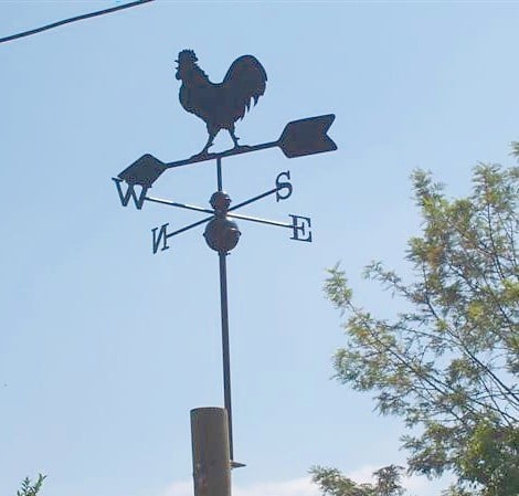
Just a couple of photo’s of your Rooster mate.
Regards Brian Goodey.
Hi Robert
Just a couple of photo’s of your Rooster mate.
Regards Brian Goodey.

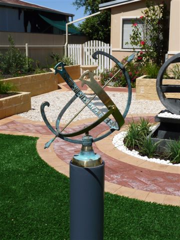
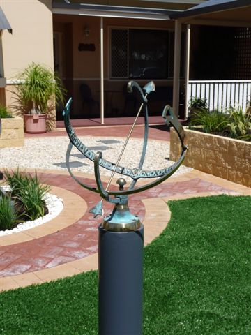
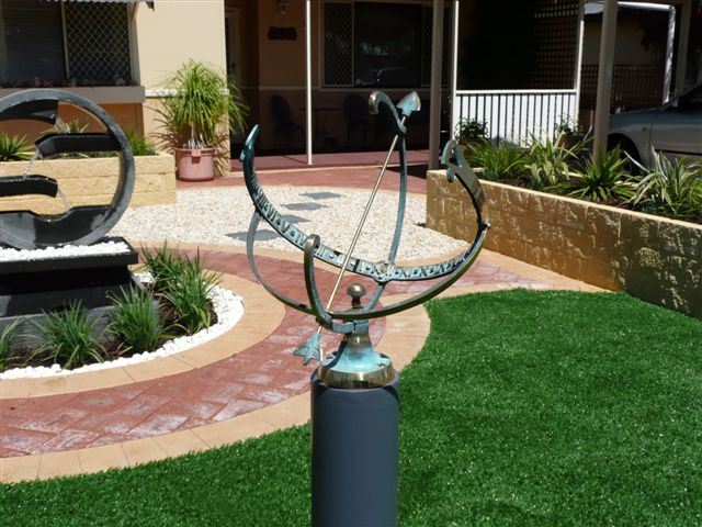
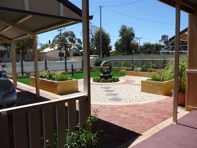
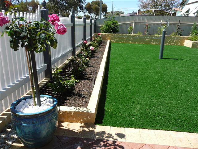
As promised, here are some of the photos of our new front garden and of course the sundial which we bought from you in June. It has created much interest and Arthur enjoys going out and checking the time. We had a very old fashioned cottage garden prior to the ‘makeover’ and a large front lawn which took a lot of water plus an iron fence and hedges. Thank goodness now for synthetic grass and raised garden beds. We have had a lot of pleasure creating our new garden and all the plants and shrubs are growing well with minimum water usage now.
We were delighted to win 2nd prize in the Kalgoorlie-Boulder water-wise garden competition last week. And today I have had the local paper take photos and do an interview for an article entitled “My Garden” , so if they mention the sundial I will send you a copy.
Kind regards
Jenny Anderson
The picture below shows how the screw or nail holes can be used to attach the Happy Daisy Windvane in an upright position.
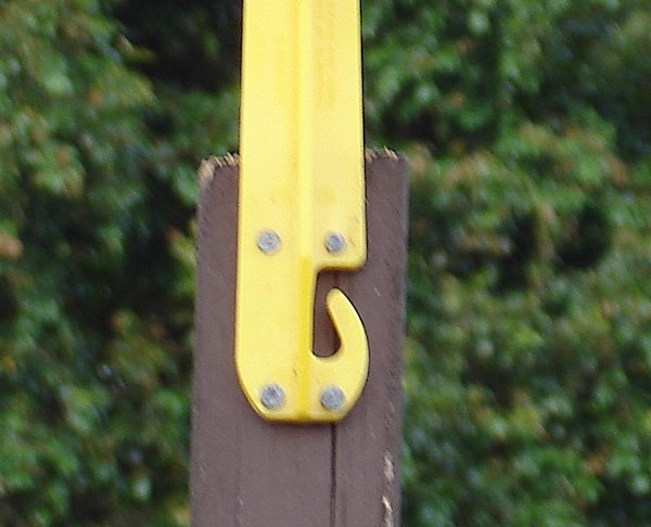
However if you want to suspend the Happy Daisy from a tree or a pergola, a clothes line or the eaves or facia board you will be able to use the hook (and it is designed not to be able to be blown off.
Quick and easy to install, It all just clicks together.
To Assemble your Happy Daisy Wind Vane.
There are 3 parts – the Body, the Stem and the Fan
Step 1. Press the tip of the body int the hole in the centre of the Fan until it clicks into place.
Step 2. Press the tip of the stem into the hole in the body until it clicks into place….It’s as simple as that!
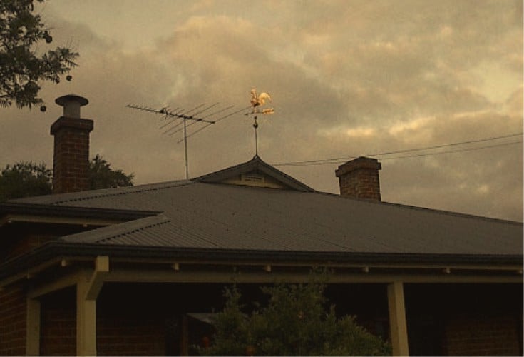
Thanks Robert. Yes, we are very pleased with your product. Here are some photos of our weathercock greeting the dawn on Thursday.
We pondered long and hard where to place him but felt that he is too beautiful for the backyard so we decided to be brave and put him on the peak of the roof – where a true -blue rooster should be! If he was a weather-hen, well, the back-yard would be OK.
Hopefully he will be safe there.
Once again, many thanks
George Gatenby
APPLICATION
This section applies to all licensed aerodromes.
INTERPRETATION
Expressions used in this section have the same meaning as in section 92.1
REQUIREMENTS
For the purposes of subregulation 89S (2) of the Civil Aviation Regulations 1988, this subsection sets out:
Note: CASA may issue directions under subregulation 92 (2) of the Civil Aviation Regulations 1988 requiring additional wind direction indicators to be provided at an aerodrome.
REQUIREMENTS

When using the cable ties to attach the windsock to the windsock frame, ensure that the cable tie’s ‘buckle’ is inside the rim to avoid the windsock material becoming damaged by rubbing on it. Once fitted, cut off the cable tie excess length.
Windsocks will not function correctly if the mouth is not vertical and facing into the wind.
The cable ties should be tight enough to restrict the movement, so that there can be no wear from rubbing of the windsock against the frame.
The windsock side seams should be at the 9 and 3 o’clock positions. (Along side each other, not top and bottom.)
To increase the life of the windsock, remove and rotate 180° after six months, then the following six months, remove the windsock again and turn inside out, re-hang with seams at the sides, then after another six months (depending on the condition) rotate windsock 180° again.
The above actions will more than double the windsock life.
Windsocks are not repairable, a torn windsock may give a false wind speed and direction.
Any windsock will perform at its best without any wind sheer influence from buildings, roof angles, trees, or orographic influences, so where possible consider placing the windsock at a distance greater than 25m from any other standing object, if this is not possible or practical, increase the height of the support as much as possible. Regulation height for a windsock is 6.7m (22ft) for 8 and 12 foot length windsocks.
This measurement is from the ground to the lower rim of the windsock.
This height requirement is not applicable to ‘Wind Indicators’ of windsock design and shape. There are 4 or 6 foot length (120cm and 180cm).


Windsock Material for 8 and 12 Foot Windsocks.
Made of compressed nylon, the windsock has the smooth side on the outside. When it gos through the rollers, it has the appearance of woven material, but it is continuous two sheets of compressed nylon. There are absolutely no gaps in the surface of the material.
It is self washing, and so this does not aid the adhesion of logos and sign writing, but sign writer plastic signs can adhere, but for how long? There are no guarantees.
There are 2 grades: Grade 3 and Grade5. (3 ounce/square foot for the standard windsock, and 5 ounce/square foot for the heavy duty windsock.)
One of the manufacturers is Canvaco.
The material is ‘Hot Needle Stitched’ and is also triple stitched.
The hoop, which is sewn in, is like grey electrical conduit.
The material does not stretch eg. Shirt material has a stretch factor of 4% and this materials’s stretch factor is approx. 1% – 1.5%.
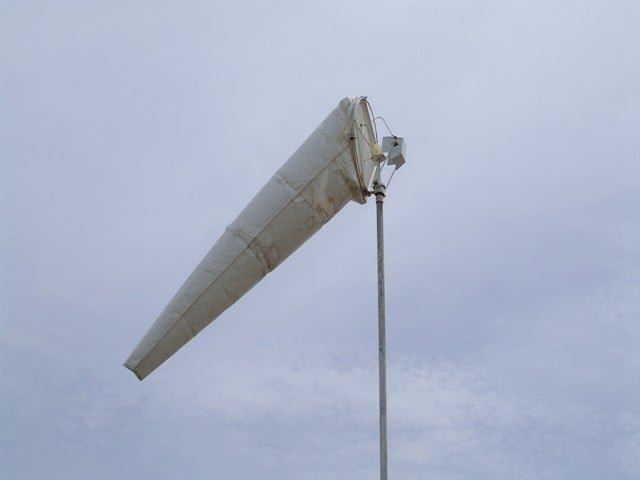
These are available in white, or yellow, and are also available in a choice of standard weight or heavy duty versions. the heavy duty version being for places of extreme wind, cyclone prone, or tropical areas.
The 8 & 12 foot windsocks are calibrated for Aviation use, fitted with an internal hoop and four large attach eyelets, and is supplied with heavy duty cable ties to attach to a 2ft diameter frame for the 8ft windsock, or a 3ft frame for the 12ft version.
The heavy duty windsock will outlast the standard weight by an estimated 50% under the same give conditions.
The standard weight windsock is slightly more ‘active’ in very light wind conditon.
12ft windsocks are the ‘standard’ for use at licenced and council airstrips and airports.
It is quite possible that there are several ‘primary’ windsocks at an airport, (one for each runway, and often one near the end of each runway.
Colour choice of windsocks for non commercial use is simply a matter of what stands out the best against the background colour as seen from the air. Yellow is easier to see against a background of sky, or as seen from the ground. Both colours illuminate well with the 12 volt lighting option, as the materials used have good fibre optic qualities.
8 & 12 ft Windsock Support Frames
These are made of 304, 316, 320 and 4000 grade stainless steel.
The 8 ft windsock frame has a 24″ (600mm) diameter rim, and the frame for the 12′ windsock has a 36″ (900mm) diameter rim. These frames may be fitted with internal 12 volt lighting…. See the”Windsock Illumination” section below:
The sealed ball bearings, that are used top and bottom, should never require any lubrication or attention. The top bearing is also capped with a seal that is a tight press fit to the centre shaft, and offers further protection to the top bearing.
The base plate of the frame is a 10mm plate with studs at 50 & 80mm spacing, stainless washers and Nylock nuts are supplied for fitting either directly or via the “Welding Adapter”.
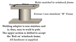 As the frame is stainless steel, (Which will not weld to ferrous metals.) thus the ‘Welding Adapter’ is recommended if the intention is to attach the frame to a metal pole end.
It is pre-drilled to match the frame stud pattern and base, made of malleable low carbon ferrous metal, that has been selected for ease of welding, using either gas, or electric arc methods.
The support frames are made for extra long life, and carry a 25 year replacement warranty. The same frames are also available (By special order) made from 316 grade stainless steel, and are ideal for offshore oil-rigs and other highly corrosive environments.
Windsock Illumination
Windsock illumination is available for the 8 and 12 foot windsocks. This operates from any 12 volt power supply, motorcycle or automotive battery, simply using battery clips or plug in using standard automotive cigarette lighter.
The lighting is 50 watt, halogen, and draws only 4 amps. (Less than a low beam headlight.) It is 100% reliable, and maintenance free. Solar charging, and remote switching are (add on) options. A spare 3000 hour life bulb/reflector is supplied.
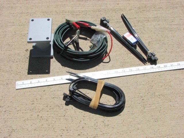
Cables and Ties as supplied in the lighting kit, including spare bulb.
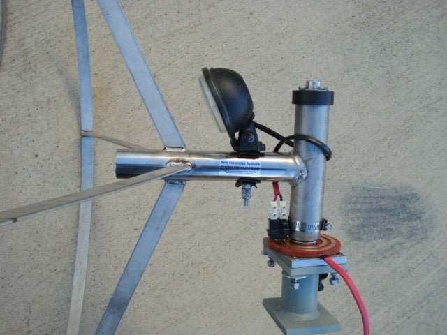
Lighting on earlier frame.
Windsock to Frame
Attach windsock to frame using the cable ties supplied, keeping the longitudinal seams of the windsock at the 3 & 9 o’clock positions. The cable ties should be tight enough so that the windsock is restricted form rubbing on the frame rim.
Windsock Frame to Vertical Support
Any suitable support pole or pipe may be used to gain the required windsock height.
If a pipe is being used, insert a bolt or a pin, through the upper hole in the support rod, then insert the rod into the pipe. A rubber cap, such as a chair leg end piece, may be used to cover the join.
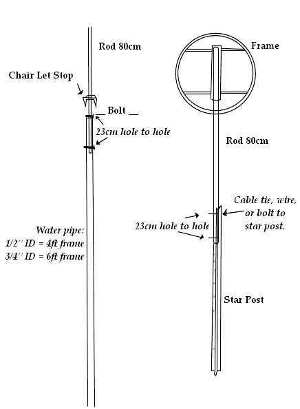
Note that the 23cm space between the holes of the frame support rod, will match up with the hole spacing of most BHP metal star posts and may be directly attached using wire, bolts or cable ties.
This method is well suited to a 4 foot windsock; and using two star posts joined, will well suit a 6 foot windsock. (The extra height needed, due to extra length.)
Tape over any sharp parts that are within the sweep of the windsock, or cut a hole in a plastic spray can lid, a small tin can, or cut the base out of a plastic bottle, then sleeve onto the support rod in order to cover any rough projections that could snag the windsock at this joint.
For a more permanent windsock installation, the star post section may be covered with any suitable 50mm PVC vent pipe so that there are no external sharp parts that could cause windsock damage. This pipe is readily available at around $6/m
It is recommended to snip the cable ties and rotate the windsock, top to bottom (180°) on a yearly basis.
Standard cable ties may be used, the black ties tend to be more ultraviolet resistant than the clear ones, and as a result the black ones should last longer.
It is important that the windsock pole and frame is exactly vertical, or the windsock will constantly swing to one side.
The 4 & 6 foot windsocks are available in ripstop, they are chemical & UV resistant, and of a lightweight sailcloth material in white, yellow, pink or orange.
White has the least problem with fade, Yellow can normally be see the greatest distance, and tends to attract attention more than the white. Pink is used on grassland and forest areas, where white or yellow blossoms are possible, and orange is used in snow areas only.